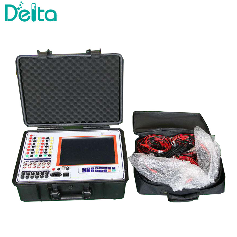
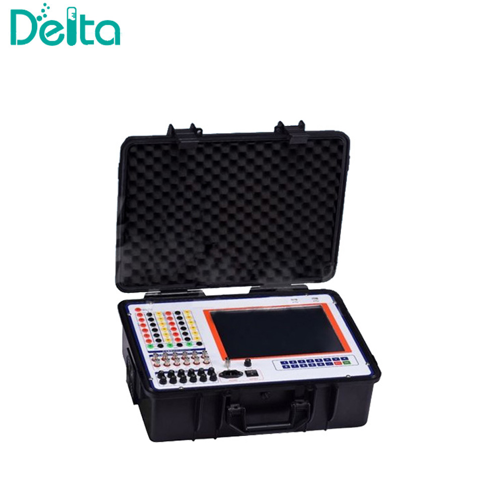
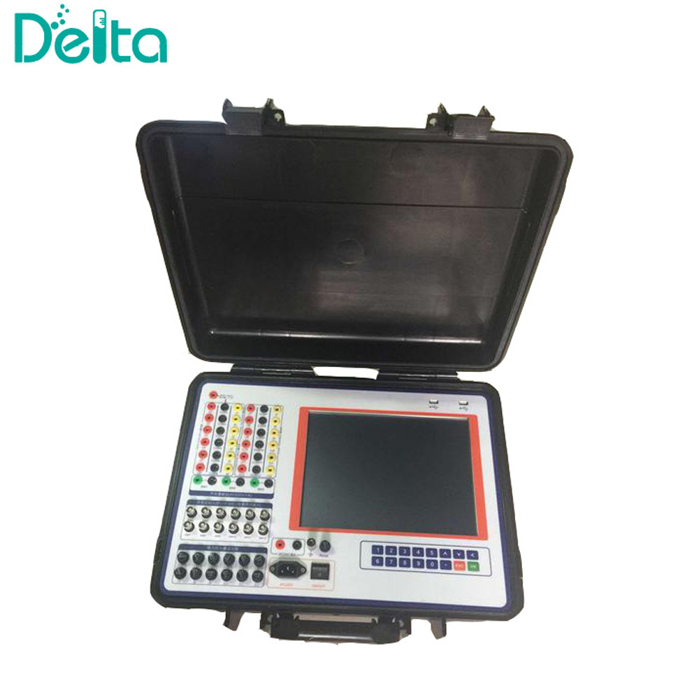

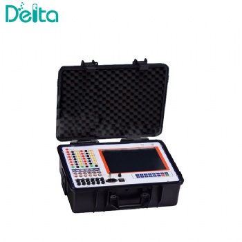
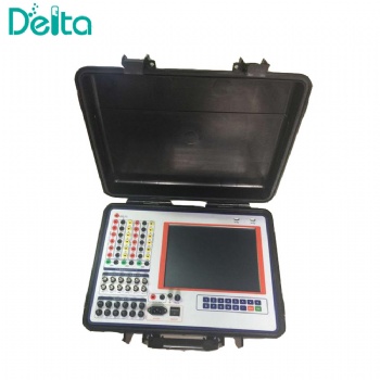

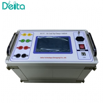
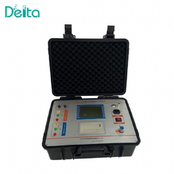
SR-601 Portable Power Generator Instantaneous Signal Recorder
It can do following tests for motor (power generator): No-load test, Short circuit test, Motor excitation step response test, Motor excitatory de-excitation test, Motor load rejection test and grid synchronous connection test and also on.
SR-601 Portable Power Generator Instantaneous Signal Recorder
Introduction:
Power Signal Recorder is designed for power signal recording.
The power generator test items are integrated at the tester.
It can do following tests for motor (power generator): No-load test, Short circuit test, Motor excitation step response test, Motor excitatory de-excitation test, Motor load rejection test and grid synchronous connection test and also on.
The software components can applied to make curve analysis, math calculation, RMS calculation, power analysis, three phase sequence analysis, frequency spectrum analysis, harmonic analysis, curve correlation analysis, picture edit and vector sequence analysis and so on. All the test data and curve can be converted to be WORD/EXCEL test report document. The entire curve in the scope of tester can be converted to be JPG file and saved to PC for further report making.
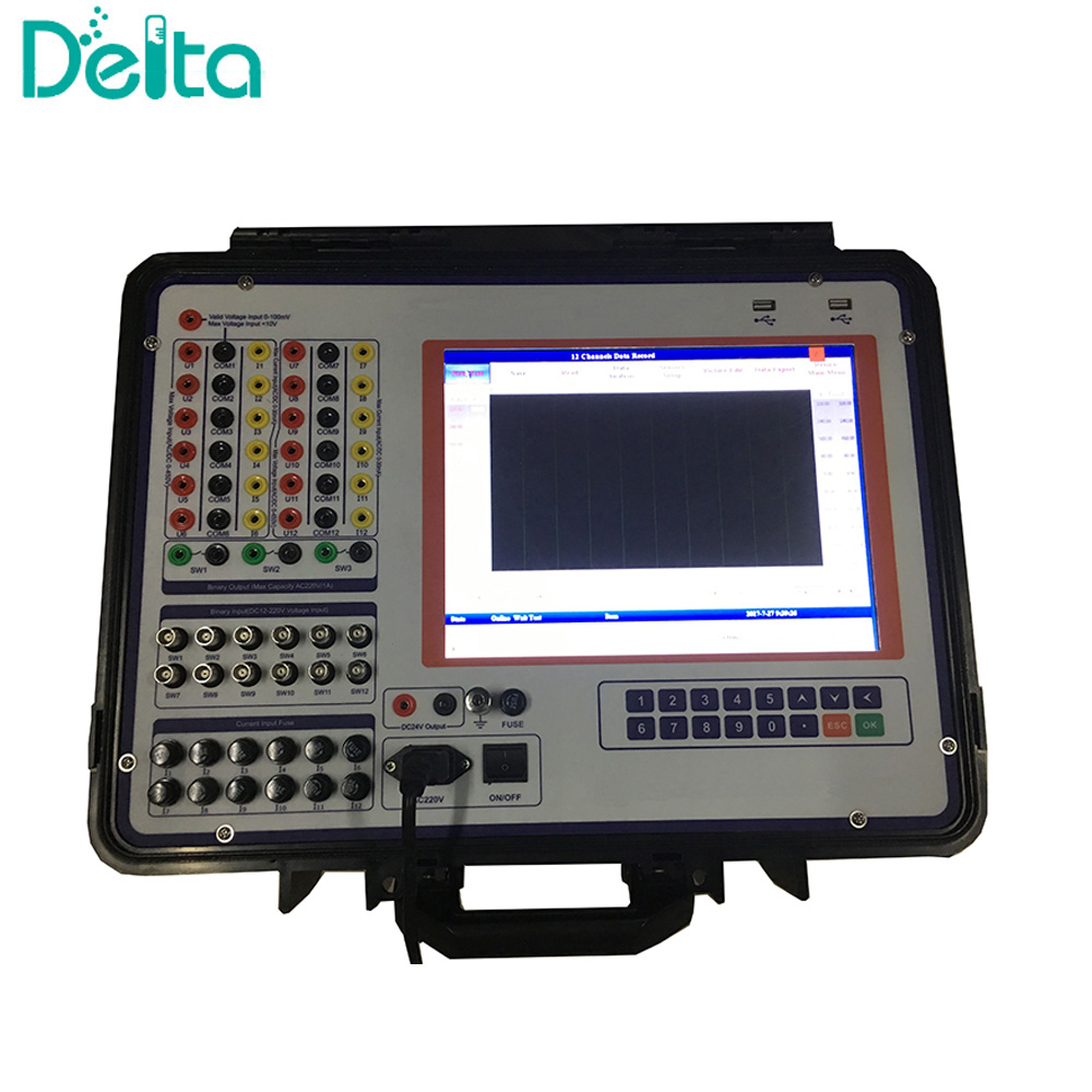
There are 12 channels analog signal input, 12 binary signal input and three relay contact output in the tester. The maximum sample rate of the tester is 100Khz. It can finish almost all the data record tasks for normal power system test. All the input channels are isolated from each others, so that all the different circuit connected to the tester will not affect each other.
Specifications:
No. | Item Name | SR-601 Portable Power Generator Instantaneous Signal Recorder |
1 | Analog signal sample channels | 12 |
2 | Optional ranges | -450V~450V,-100V~100V,~10V~10V,-20mA~20mA, -100mV~100mV(only 1 channel) |
3 | Sample error | -450V~450V: error<0.5V -100V~100V: error <0.2V -10V~10V: error <0.01V -20mA~20mA: error <0.02mA -100mV~100mV: error<0.5mV |
| 4 | Input resistances for different channels | -10V~10V: 820K -200V~200V: 820K -400V~400V: 820K -20mA~20mA: 820K -100mV~100mV: 10M |
5 | Binary signal input interface | 12 |
6 | Binary signal voltage ranges | DC 12~220V |
| 7 | Display | 12.1 inch LCD screen |
| 8 | SD Storage | 32G |
9 | Power supply | AC220V±10% |
10 | Power frequency | 45Hz-65Hz |
11 | Power consumption | ≤60w |
12 | Working environment | -10~50ºC, humidity ≤85%RH |
13 | Dimension | 448mm*260mm*150mm |
14 | Weight | <10kg |
Software Features:
1. The recorded signal display in curve by scope in the tester in real time. Multi curve analysis is included in the tester. User can make zoom in/out and data location from the sampled curves.
2. The recorded curves can be edited, add text tag, change the color and so on. So that users can make report in they prefer curves and display mode.
3. The Fourier transformer tools can get the amplitude and phase spectrum of the recorded curves.
4. All the curves can be selected as x coordinate and y coordinate to make the correlation curve of those two curves.
5. The harmonic tools can get the maximum 1024 times harmonic for recorded curve.
6. The math tools can make add, decrease, multiple, divide and integrations for any curves in the scope.
7. Users can make RMS, Power watt calculation for any recorded curves in the scope.
8. The recorded three phase voltage and current signals can be applied to calculate the sequence, active power, reactive power, apparent power, power factor and so on.
9. Draw vector group picture for all the AC signals recorded.
10. The signal curve display mode can be set by software. Both the instantaneous curve or RMS curve can be showed by the tester.
11. The motor no-load test, short circuit test, excitation system step response test, de-excitation time constant measurement, frequency-voltage characteristic curve measurement. Load rejection test, grid synchronous connection test template are integrated in the tester. The test results for those templates will be automatic if the template is used for records.
12. All the data and results can be converted to be word and excel test report.
13. The curve can be marked use text automatic. That makes the report making more simple
14. All the channels name and unit can be redefined by users.
15. All the test configuration and test setting will be saved automatic.
16. The sensors setup window can make tester shows the real value such as high voltage, high current, pressure and so on direct after user configure the sensors factors
17. All the data and report can be saved to U-disk. So that users can review and make report from PC.
18. The protection unit of the tester system disk can recover the software and system every time when it reboot. But all the test data will be saved.


 Send Email
 售前客服
售前客服